Technical Innovations
CMU and Boeing team on combat vehicle
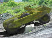 The hybrid-powered, unmanned ground combat vehicle, Spinner, being built by Carnegie Mellon University (CMU), will be designed to negotiate and move swiftly over major terrain obstacles, withstand a moderate crash, and rapidly recover and operate while inverted. (Image courtesy of Boeing.) |
The Defense Advanced Research Projects Agency (DARPA) has awarded $5.5 million to the National Robotics Engineering Consortium (NREC) of Carnegie Mellon University (CMU) to build and test a prototype robotic unmanned ground combat vehicle (UGCV). The vehicle will be the first attempt at an autonomous ground combat vehicle that can operate on all types of terrain. According to John Bares, Project Manager and Director of the NREC, CMU is "designing a new vehicle from the ground up that can take full advantage of the fact that it will not accommodate a human crew."
The award follows two earlier awards—the first to define the concept and the second for further detail design, in which a team of NREC researchers worked with subcontractors that included Boeing, PEI Electronics, and Timoney Technology to build a six-wheeled testbed machine similar in size to the final prototype.
Boeing is building the vehicle's frame, hull, nose, and payload compartment in Seattle, taking advantage of the latest composite materials and fabrication processes, together with a unique structural concept, that will be extremely crash resistant," said Wayne Hammond, Boeing UGCV Program Manager. Boeing's Unmanned Systems organization also includes the X-45 unmanned combat air vehicle and ScanEagle unmanned aerial vehicle.
 The hull configuration of CMU's six-wheel drive Spinner will offer a large continuous payload bay that can rotate payloads in upright or downward positions. The vehicle will have a mass of about 7574 kg (16,700 lb) with full payload. (Images courtesy of CMU.) Click to enlarge |
Timoney, based in Meath, Ireland, is in charge of the unique invertible suspension and wheel drive units that will enable the vehicle to operate upside down after a rollover. Huntsville, AL-based PEI, a business unit of Integrated Defense Technologies, will supply the vehicle's battery and power-management system and key vehicle control software and hardware.
High-torque, wheel-mounted propulsion motors from UQM Technologies will power the Spinner. According to William Rankin, UQM President and CEO, the company nearly doubled the torque delivery capability of its existing high-performance propulsion motors to meet performance requirements of the Spinner. The vehicle's final assembly will be by CMU in Pittsburgh.
CMU and UQM are also working together on the development and preliminary design of a propulsion system for the future Gladiator tactical unmanned ground vehicle (TUGV). The TUGV is planned as a robust, compact, unmanned multi-purpose vehicle system that will possess a scouting and direct engagement capability. The teleoperated, semi-autonomous vehicle will provide the U.S. Marine Corps with remote reconnaissance, surveillance, and target acquisition; nuclear, biological, and chemical reconnaissance; obstacle breaching; and direct fire capability to neutralize threats.
- Jean L. Broge
Robotron controls induction hardening
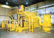 Big Yellow is used by a major diesel engine manufacturer for induction hardening of crankshaft pins and journals. |
Induction hardening of diesel crankshaft pins and journals has been industry-standard since the 1930s, according to Robotron-Elotherm, Inc., and the process is still evolving as new inductor, power supply, and control technologies give engineers the tools needed to achieve previously unattainable results. The company used such new technologies to design and build a highly automated induction-hardening system engineered to process four types of crankshafts for six-cylinder diesel engines ranging in displacement from 7-12 L.
Called "Big Yellow" by Robotron, the system combines state-of-the-art power control and inductor technologies, field-proven shuttle-type part transfer, and precision mechanical part rotation to produce 25 crankshafts/h. Changeover from one crank to another can be done in less than 45 min and requires only replacement of inductors, chuck inserts, and rests. Robotron's challenge was to reliably process the pins and journals despite the fact that the cheeks between them were much thinner than normal for crankshafts of their size.
"At first glance, processing a crankshaft looks like it should be really easy," said Rudy Schwarz, Induction Heating Product Manager for Robotron. "But that is not the case. There is a tremendous mass difference between the pins and journals and cheeks, and that can lead to all sorts of complications, with one feature or the other acting as a heat sink to complicate heat flow dynamics." Even worse, he added, the relationship is not uniform. At top dead center on a crank pin there is very little cheek metal, while at bottom dead center on the same pin, the heated area is virtually surrounded by a huge heat sink. "If you simply put an inductor in place and turn on the power, you will overheat the cheeks at top dead center and underheat the pin in the fillet area at bottom dead center," Schwarz explained. The journals are more uniform in cheek mass, but they pose problems of their own, he noted.
Big Yellow uses a "pulsed" power system to meet the challenge of uniformly processing pins and journals. The system varies the amount of energy delivered by the inductor in real time as the pin or journal is rotated under it to produce uniform heating. The trick is to synchronize the part rotation with the power pulsing in real time, and to do it fast enough to meet the customer's throughput requirement.
The system has three converters to provide the energy required to process six pins and seven journals on four crankshafts—all controlled through a programmable logic controller (PLC) operating near the top end of its capabilities to provide the 10-ms response time required by the system to continuously vary the output as the crank rotates.
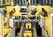 A hardened crankshaft is checked in the TIR measurement station to confirm straightness. |
Big Yellow is manually loaded by an operator who places a green crankshaft onto a set of roller rests on the system shuttle. A bar-code reader identifies the part and registers it with the PLC for quality tracking purposes. The shuttle then moves into position to retrieve a processed crank from the chucks that rotate it through the induction-hardening process stations. The heated crank is placed on a set of V-blocks on the shuttle, which then positions the previously loaded green crank for pickup by the chucks.
Once the green crank is in the chucks, the shuttle moves the processed crank to a cool-down station, and then to a total indicated run-out (TIR) measurement station, where it is checked for distortion. From there, the unit is moved to a load/unload station, where the operator replaces it with a green part to begin the cycle again. While this is happening, the crank inside Big Yellow is being moved under the pin-processing inductors. In the first operation, pins #1 and 6 are processed, then the crank is re-oriented to process pins #2 and 5, and then #3 and 4. Six separate inductors are used to process the pins.
Then the crank is shuttled into the journal processing station, where inductors are positioned over journals #1, 2, 3, 5, 6, and 7. Bearings #1, 2, 6, and 7 are then heated and quenched, followed by heating and quenching of bearings #3 and 5. Finally, the six inductors that have been used are raised away from the crank, and the inductor for journal #4 is lowered to process the last bearing. Upon completion of the processing cycle, the hot crank is placed on the shuttle and moved through the cooling and test stations prior to it being unloaded.
The cranks are self-tempering, owing to precise control of thermal inputs. The advanced process control system monitors the power consumption of each inductor throughout each cycle and compares it to known set standards to calculate the effective amount of energy imparted to the workpiece. "Once we know that," Schwarz said, "we can reliably predict the effectiveness of the hardening cycle, and also of the subsequent mar-tempering process. By doing this in real time while the crank is being processed, we can optimize the individual heating operation and increase the production of good parts."
- Patrick Ponticel